Ultra-Lift Calf Hutch Bedding Manual
Listed below are common practices that may or may not be applicable to the products described in this manual.
Look for the Safety Alert Symbol

The SAFETY ALERT SYMBOL indicates there is a potential hazard to personal safety and extra precaution must be taken. When you see this symbol, be alert and carefully read the message that follows it. Hazard control, and accident prevention are dependent upon the awareness, concern, prudence and proper training of personnel involved in the operation, transport, maintenance, and storage of equipment.
Be Aware of Signal Words
A signal word designates a degree or level of hazard seriousness. They are:
DANGER:
Indicates a hazardous situation that, if not avoided, will result in death or serious injury.
WARNING:
Indicates a hazardous situation that, if not avoided, could result in death or serious injury.
Listed below are common practices that may or may not be applicable to the products described in this manual.
Safety at All Times
Careful operation is your best assurance against an accident. All operators, no matter how much experience they may have, should carefully read this manual and other related manuals before operating this power machine and this implement.
- Thoroughly read and understand the “Safety Label” section. Read all instructions noted on them.
- Do not operate the equipment while under the influence of drugs or alcohol as they impair the ability to safely and properly operate the equipment.
- The operator should be familiar with all functions of the power machine and attached implement, and be able to handle emergencies quickly.
- Keep all bystanders away from equipment and work area.
- Operate power machine and controls from the driver’s seat only.
- Never dismount from a moving power machine or leave power machine unattended with engine running.
- Do not allow anyone to stand between implements and power machine while attempting to connect or disconnect them.
- Keep hand, feet and clothing away from power-driven parts.
- While transporting and operating equipment, watch out for objects overhead and along side such as fences, trees, buildings, wires, etc.
- Do not turn power machine so tight as to cause hitched implement to contact the power machine’s rear wheel.
- Store implement in a safe and secure area where children do not plate. When needed, secure implement against falling with support blocks and/or shipping locks.
Safety Precautions for Children
Tragedy can occur if the operator is not alert to the presence of children. Children are generally attracted to implements and their work.
- Never assume children will remain where you last saw them.
- Keep children out of the work area and under the watchful eye of a responsible adult.
- Be alert and shut the implement and power machine down if children enter the work area.
- Never carry children on the power machine or implement. There is not a safe place for them to ride. They may fall off and be run over or interfere with the control of the power machine.
- Never allow children to operate the power machine, even under adult supervision.
Power Machine Shutdown & Storage

- If engaged, disengage power take-off.
- Park on solid, level ground and lower implements to ground or onto support blocks.
- Put power machine in part or set park brake
- Turn off engine and remove ignition key to prevent unauthorized starting.
- Relieve all hydraulic pressure to auxiliary hydraulic lines.
- Wait for all components to stop before leaving the operator’s seat.
- Use steps, grab-handles and anti-slip surfaces when stepping on and off the power machine.
Use a Safety Chain
- A safety chain will help control drawn machinery should it separate from the power machine or tow vehicle.
- Use a chain with the strength rating equal to or greater than the gross weight of the towed implement
- Attach the chain to the power machine’s or tow vehicle’s draw bar support or other specified anchor location. Allow only enough slack in the chain to permit turning.
- Always hutch the implement to the machine towing it. Do not use the safety chain to tow the implement.
Tire Safety
- Tire changing can be dangerous and must be performed by trained personnel using the correct tools and equipment.
- Always properly match the wheel size to the properly sized tire.
- Always maintain correct tire pressure. Do not inflate tires above the recommended pressures shown in the Operator’s Manual or printed on the tires themselves.
- When inflating tires, use a clip-on chuck and extension hose long enough to allow you to stand to one side and NOT in front of or over the tire assembly. Use a safety cage if available.
- Securely support the implement when changing a wheel.
- When removing and installing wheels, use wheel handling equipment adequate for the weight involved.
- Make sure wheel bolts have been tightened to the specified torque.
Practice Safe Maintenance


- Understand procedure before doing work. Refer to the Operator’s Manual for additional information.
- Work on a level surface in a clean, dry area that is well-lit.
- Lower implement to the ground and follow all shutdown procedures before leaving the operator’s seat to perform maintenance
- Do not work under any hydraulically supported equipment. It can settle, suddenly lead down, or be lowered accidentally. If it is necessary to work under the equipment, securely support it with stands or suitable blocking beforehand.
- Use properly grounded electrical outlets and tools.
- Use correct tools and equipment for the job that are in good condition.
- Allow equipment to cool before working on it.
- Disconnect battery ground cable (-) before servicing or adjusting electrical systems or before welding on implement.
- Inspect all parts. Make certain parts are in good condition & installed properly.
- Replace parts on this implement with genuine Hatfield parts only. Do not alter this implement in a way which will adversely affect its performance.
- Do not grease or oil implement while it is in operation.
- Remove any buildup of grease, oil, and/or debris.
- Always make sure any material and waste products from the repair and maintenance of the implement are properly collected and disposed.
- Do not weld or torch galvanized metal as it will release toxic fumes.
Prepare for Emergencies
- Be prepared if a fire starts
- Keep a first aid kit and fire extinguisher handy.
- Keep emergency number for doctor, ambulance, and fire department near the phone.
Use Safety Lights and Devices
- A slow-moving power machine can create a hazard when driven on public roads. They are difficult to see, especially at night. Use the Slow-Moving Vehicle (SMV) Sign when on public roads.
- Flashing warning lights and turn signals are recommended whenever driving on public roads.
Wear Personal Protective Equipment
- Wear protective clothing and equipment appropriate for the job such as safety shoes, safety glasses, hard hat, dust mask, and ear plugs.
- Clothing should fit snug without fringes and pull strings to avoid entanglement with moving parts.
- Prolonged exposure to loud noise can cause hearing impairment or hearing loss. Wear suitable hearing protection such as earmuffs or earplugs.
- Operating a machine safely requires the operator’s full attention. Avoid wearing headphones while operating
Use Seat Belt and ROPS
- Use of a CAB or roll-over-protective-structures (ROPS) and seat belt is recommended in almost all power machines.
- If ROPS is in the locked-up position, fasten seat belt snugly and securely to help protect against serious injury or death from falling and machine overturn.
Avoid High Pressure Fluids
- Escaping fluid under pressure will penetrate the skin or eyes causing serious injury.
- Relieve all residual pressure before disconnecting hydraulic lines or performing work on the hydraulic system.
- Make sure all hydraulic fluid connections are properly tightened/torqued and all hydraulic hoses and lines are in good condition before applying pressure to the system.
- Use a piece of paper or cardboards, NOT BODY PARTS, to check for suspected leaks.
- Wear protective gloves and safety glasses or goggles when working with hydraulic systems.
- DO NOT DELAY. If an accident occurs, seek immediate
Keep Riders Off Machinery
- Never carry riders on the tractor or implement.
- Riders obstruct operator’s view and interfere with the control of the power machine.
- Riders can be struck by objects or thrown from equipment.
- Never use the power machine to lift or transport riders.
Avoid Crystalline Silica (quartz) Dust
Because crystalline silica is a basic component of sand and granite, many activities at construction sites produce dust containing crystalline silica. Trenching, sawing and boring of material containing crystalline silica can produce dust containing crystalline silica particles. This dust can cause serious injury to the lungs (silicosis).
There are guidelines which should be followed if crystalline silica (quartz) is present in the dust.
- Be aware of and follow OSHA (or other local, State, or Federal) guidelines for exposure to airborne crystalline silica.
- Know the work operations where exposure to crystalline silica may occur.
- Participate in air monitoring or training programs offered by the employer.
- Be aware of and use optional equipment controls such as water sprays, local exhaust ventilation, and enclosed cabs with positive pressure air conditioning if the machine has such equipment. Otherwise, respirators shall be worn.
- Where respirators are required, wear a respirator approved for protection against crystalline silica containing dust. Do not alter respirator in any way. Workers who use tight-fitting respirators can not have beards/mustaches which interfere with the respirator seal to the face.
- If possible, change into disposable or washable work clothes at the work side; shower and change into clean clothing before leaving the work site.
- Do not eat, drink, use tobacco products, or apply cosmetics in areas where there is dust containing crystalline silica.
Handle Chemicals Properly
- Protective clothing should be worn.
- Handle all chemicals with care.
- Follow instructions on container label.
- Agricultural chemicals can be dangerous. Improper use can seriously injure persons, animals, plants, soil, and property.
- Inhaling smoke from any type of chemical fire can be a health hazard.
- Store or dispose of unused chemicals as specified by the chemical manufacturer.
Dig Safe — Avoid Underground Utilities
- USA: Call 811. CAN: digsafecanada.ca Always contact your local utility companies (electrical, telephone, gas, water, sewer, and others) before digging so that they may mark the location of any underground services in the area.
- Be sure to ask how close you can work to the marks they positioned.
Transport Safely
- Comply with federal, state and local laws.
- Use towing vehicle and trailer of adequate size and capacity. Secure equipment towed on a trailer with tie downs and chains
- Sudden braking can cause a towed trailer to swerve unexpectedly. Reduce speed if towed trailer is not equipped with brakes.
- Avoid contact with any overhead utility lines or electrically charged conductors.
- Always drive with load on end of loader arms low to the ground.
- Always drive straight up and down steep inclines with heavy end of skid steer on the “uphill” side
- Maximum transport speed for an attached equipment is 20 mph (32km/h). DO NOT EXCEED
- As a guideline, use the following maximum speed weight ratios for attached equipment: 20 mph (32 km/h) when weight of attached equipment is less than or equal to the weight of the tow vehicle. 10 mph (16 km/h) when weight of attached equipment exceeds the weight of the tow vehicle but not more than double the weight.
- IMPORTANT: Do not tow a load that is more than double the weight of the vehicle towing the load.
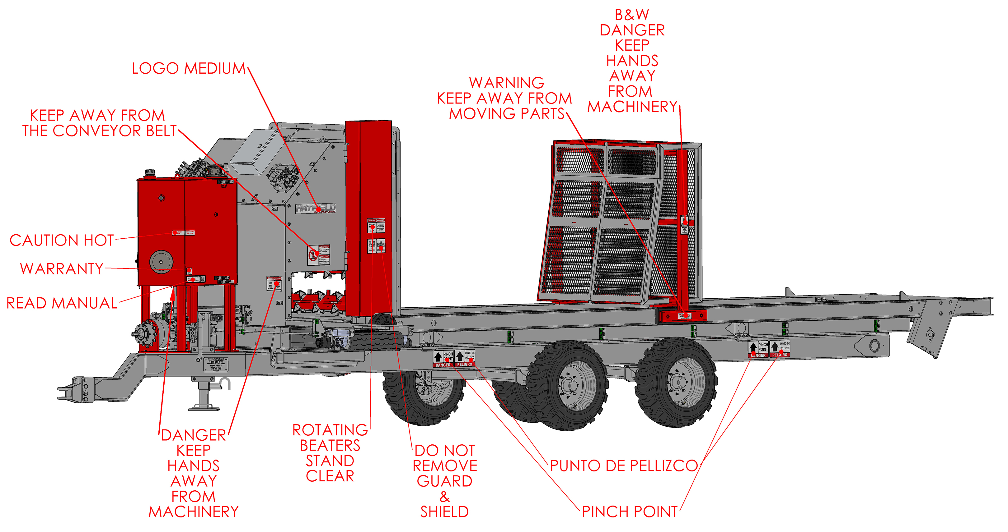
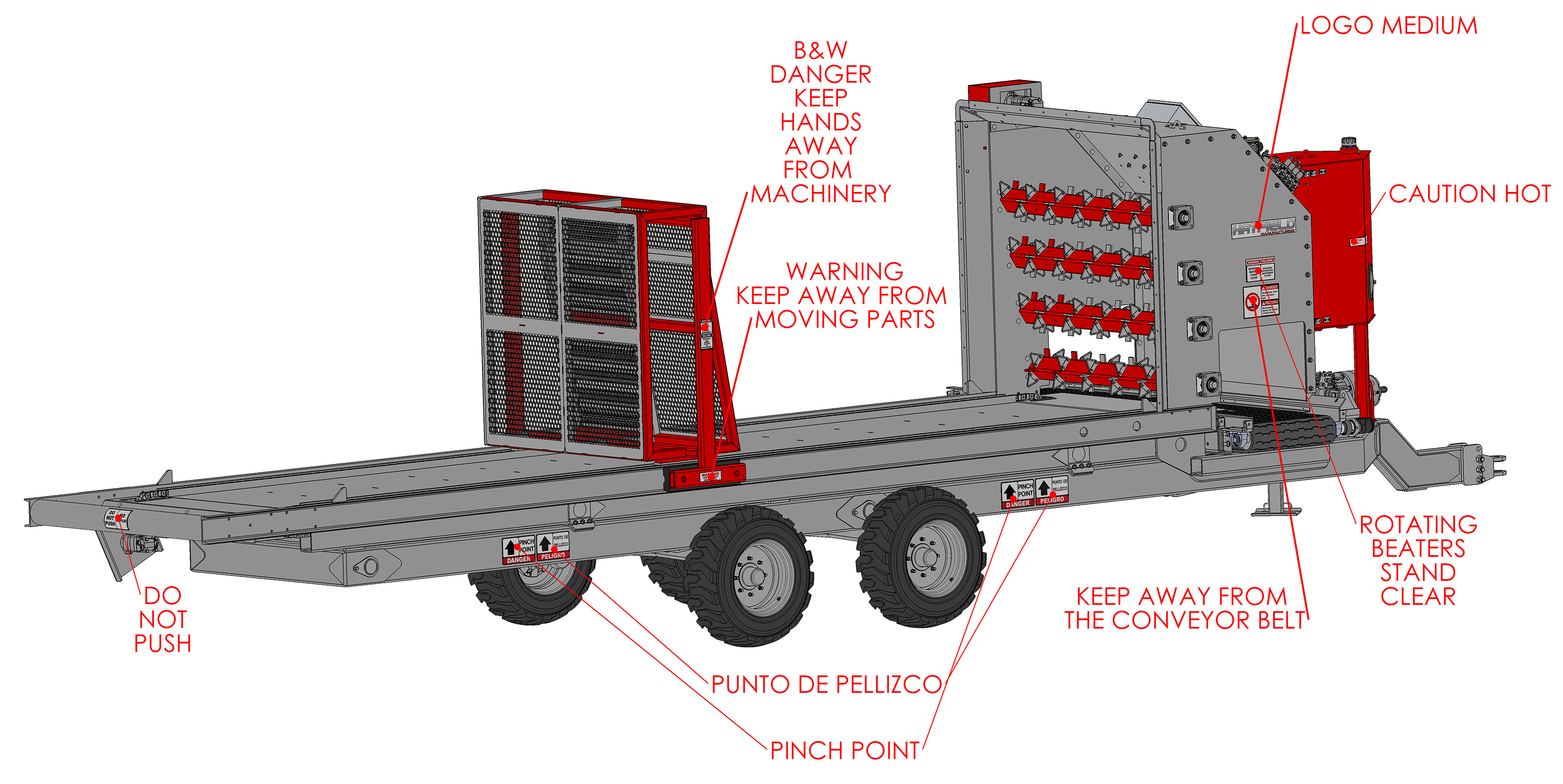
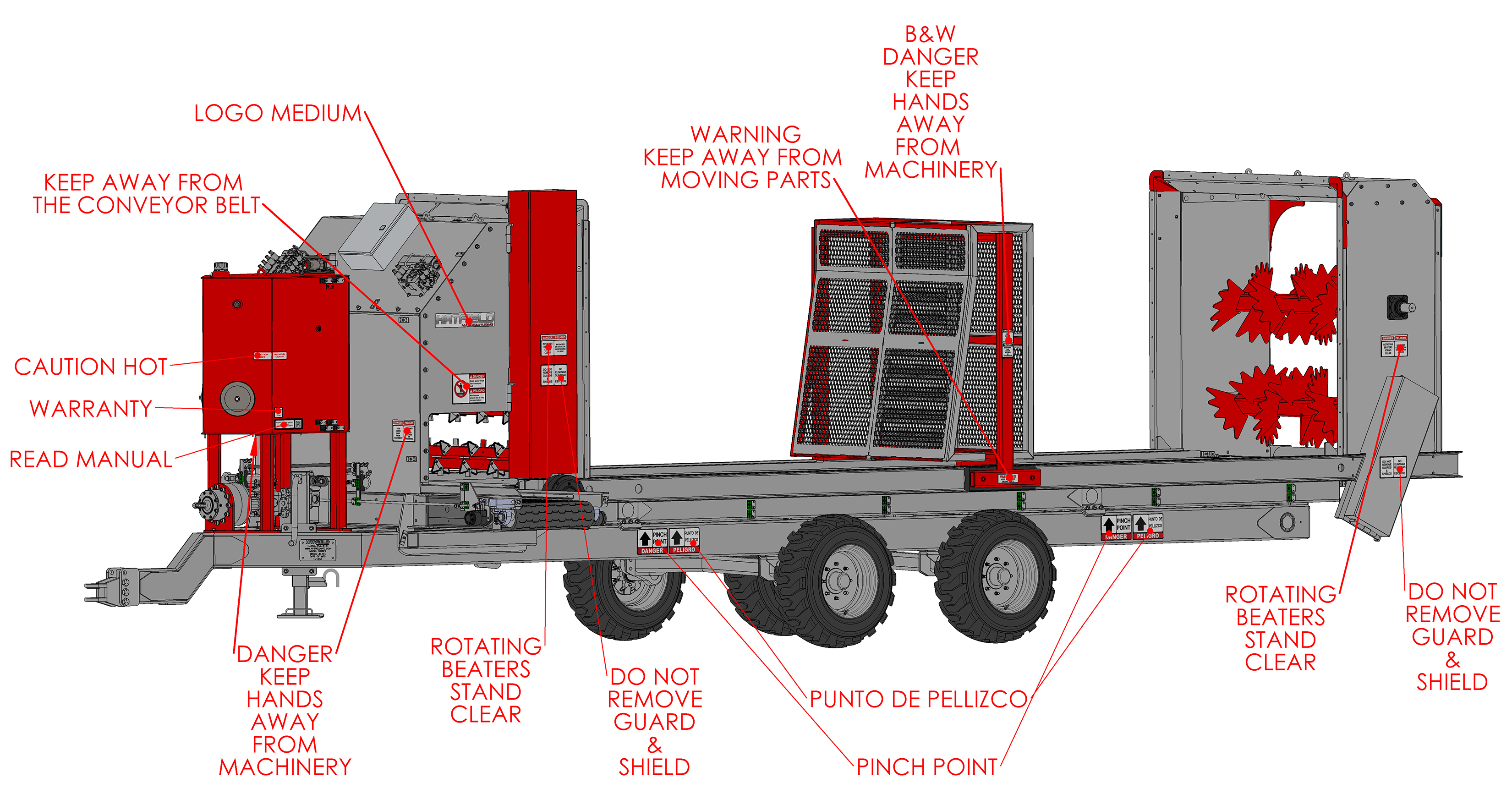
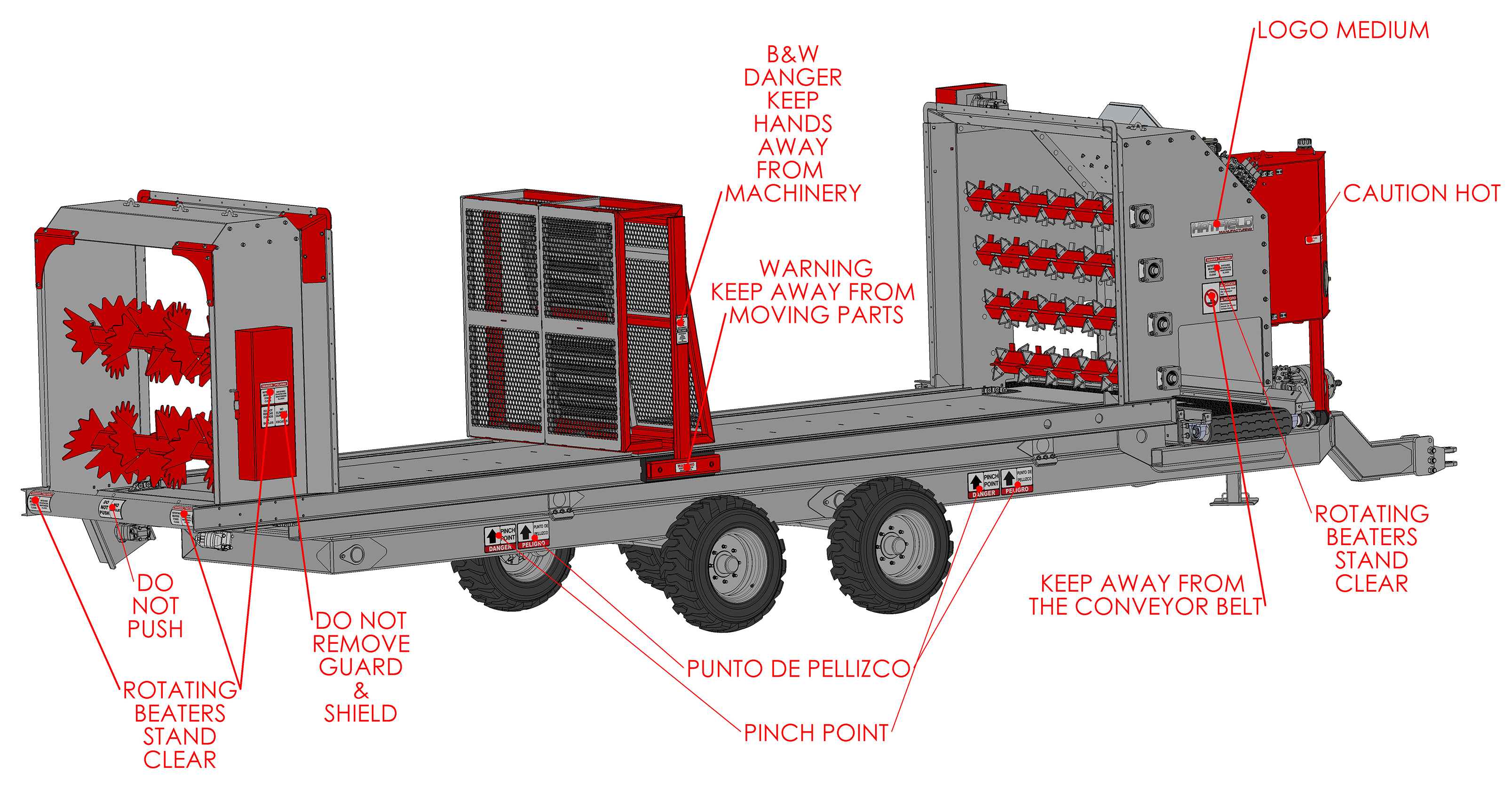
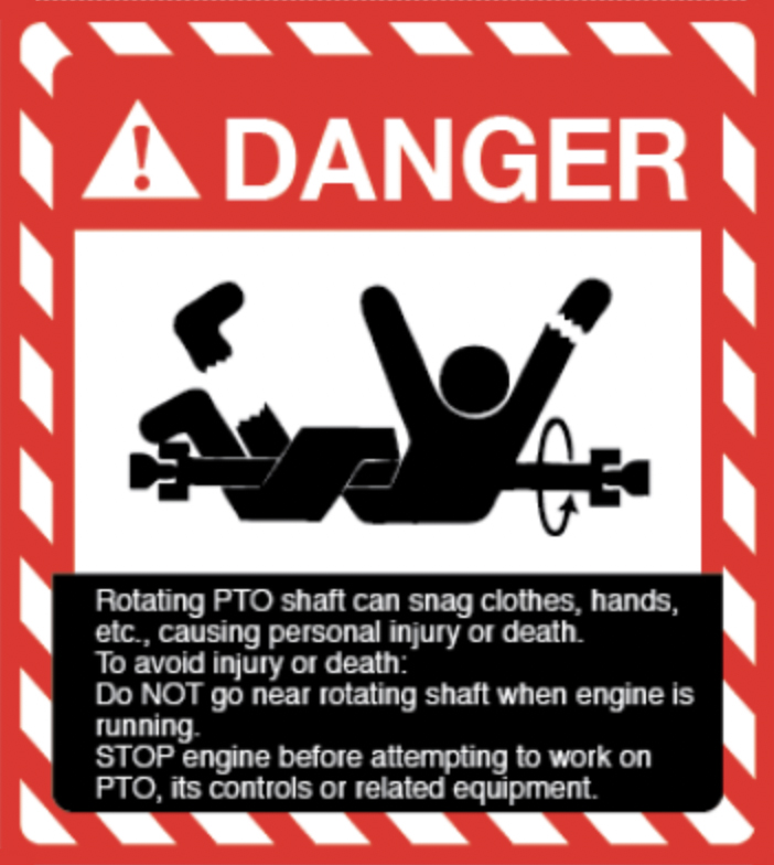
Safety Labels
Your Ultra-Lift comes equipped with all safety labels in place. They were designed to help you safely operate your equipment. Read and follow their directions.
- Keep all safety labels clean and legible.
- Refer to this section for proper label placement. Replace all damaged or missing labels. Order new labels from www.hatfieldmfg.com.
- Some new equipment installed during repair requires safety labels to be affixed to the replaced component as specified herein. When ordering new components make sure the correct safety labels are included in the request.
- Refer to this section for proper label placement. To install new labels: Clean Surface area where label is to be placed. Spray soapy water onto the cleaned area. Peel backing from label and press label firmly onto the surface. Squeeze out air bubbles with edge of a credit card or with a similar type of straight edge.
Labels for your Ultra-Lift are sold in packages containing all the safety labels you need.
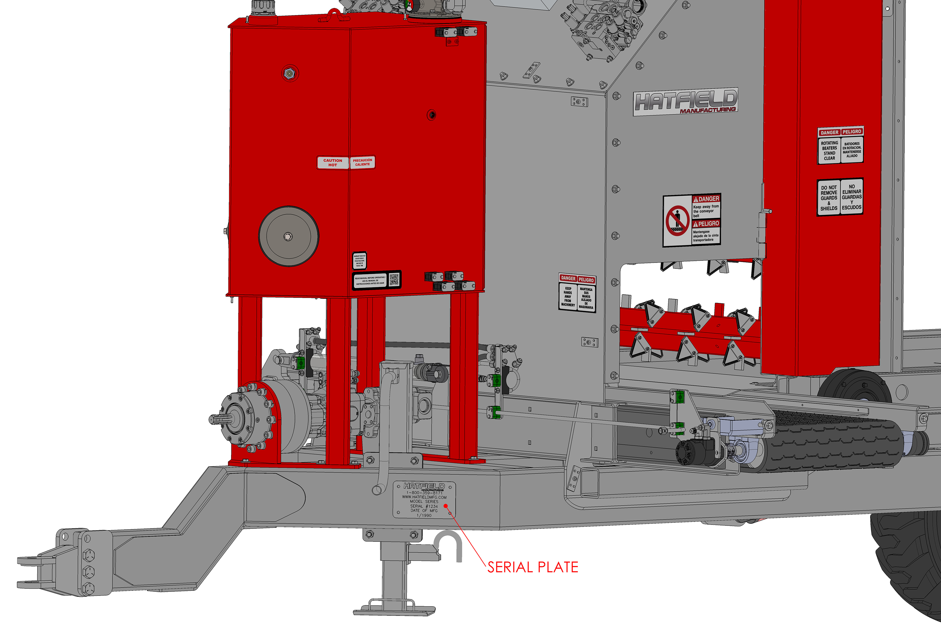
Record your machine details: Serial Number, Model Number and Delivery Date.
Ultra-Lift Conveyor Installation Guide
In order to ship your Ultralift Bedding Trailer, the conveyor must be removed. Follow these simple steps to reinstall it.
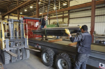
Step One
- Unstrap the conveyor and remove any packing materials that may be present. Due to its weight and size it is recommended that the conveyor be moved with a forklift or gantry crane. The conveyor must be installed from the right side (passenger side) of the trailer.
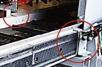
Step Two
- Position the conveyor with the conveyor motor facing forward and the farthest away from the trailer. When lining up the conveyor to slide it in, note that the channels on the trailer nest inside the channels on the conveyor. There is a cover plate on the rear side of the housing that must go on top of the conveyor. side) of the trailer.
Step Three
- Position the conveyor with the conveyor motor facing forward and the farthest away from the trailer. When lining up the conveyor to slide it in, note that the Position the conveyor with the conveyor motor facing forward and the farthest away from the trailer. When lining up the conveyor to slide it in, note that the channels on the trailer nest inside the channels on the conveyor. There is a cover plate on the rear side of the housing that must go on top of the conveyor.

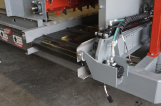
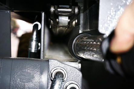
Step Four
- The hole in the hydraulic ram mount should now be lined up with the pin as shown. If it isn’t, pull the conveyor back out until it is.
Step Five
- The hole in the hydraulic ram Straighten and remove one of the cotter pins and remove the clevis pin from the end of the hydraulic ram and attach the ram to the mount making to fully bend both cotter pins.
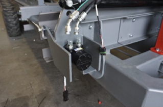
Step Six
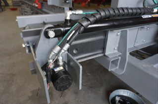
- Put a pan under the motor and remove the caps from the motor and the plugs from the lines with a 7/8” and a 13/16” wrench and connect them as shown.
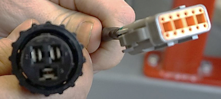
Step Seven
- Connect the three-pin sensor cable, it will only connect one way.
- Your conveyor is installed!
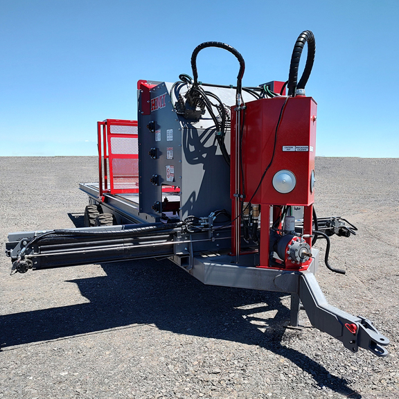
Operating the Ultra-Lift Calf Hutch Bedding Trailer

WARNING
To avoid serious injury or death:
Read all instructions before attempting to operate this equipment. Obey all warning labels on machine.
- Perform a “dry run” so that you are familiar with all the controls before adding straw and operating the trailer while driving the tow vehicle
- Never exceed 20 mph (32 km/h) while towing this trailer
- Full trailers will react differently, extra care and lower speed will be required especially on uneven terrain.
- This trailer is designed to run on a 540 rpm PTO, DO NOT connect it to a 1000 rpm PTO
- When trailer is elevated, especially with straw bales, it becomes very top heavy. Never activate the lift mechanism when trailer is on a slope or drive on uneven terrain with the lift raised.
- Never allow anyone to place any part of their body under or in the machine while it is elevated.
- Never attempt to clear a jam by hand or with an implement without first shutting off the PTO drive.
- All strings and bands must be removed from the straw bales before running them through the machine.
- This machine is designed for straw or hay only, never attempt to run any other material through it.
- To prevent damage to the conveyor, use the controls to slide it to a centered position when not in use. Leaving it sticking out one side or the other increases the risk of hitting something or someone with conveyor as you drive.
- In the event of an emergency, the fastest way to stop the moving parts of the trailer is to shut off the PTO drive in the tractor or shut off the tractor!
Hitch Mount
- This Trailer is equipped with a Clevis Style Hitch. The hitch can be unbolted to adjust the height to match the towing vehicle. Always ensure that ALL THREE bolts are used to assemble the hitch and that they are torqued to 200 ft-lb.
- To hook up the trailer, simply align the tongue BETWEEN the hitch plates and slide the Clevis Pin down through all the plates. The Clevis Pin should be secured with a Hairpin Clip.
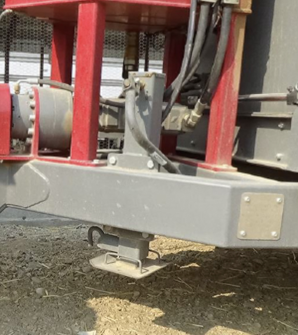
Jack Stand
- Once the Hitch Mount is secured to the tow vehicle, the Jack Crank can be wound Counter Clockwise (Anticlockwise) until the baseplate is off of the ground. Now pull on the pin that holds the jack leg, lift up on the handle and release the pin to lock the jack up out of the way, this will prevent the jack from getting damaged during trailer use.
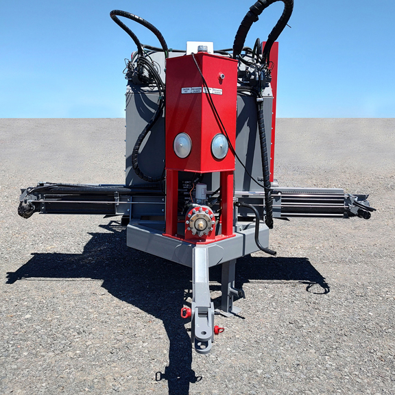
Connecting the PTO Pump
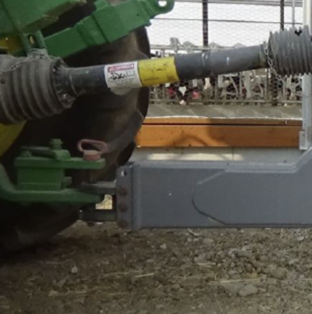
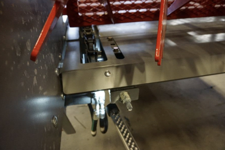
- Prior to attaching the PTO drive between the Ultralift and the towing vehicle (tractor), tractor must be turned off with the wheels chocked. The PTO shaft is marked indicating the tractor end and the implement end. IT MUST BE INSTALLED CORRECTLY. Slide PTO Link end over the spline shaft on the back of the tractor and secure the collar lock. Double check that both ends of the PTO link are securely locked on and that the sleeve covers both ends.
- Never operate without the PTO Shields in Place and secured!
- In order to operate the Trailer with the included PTO Drive Shaft safely
- The total length of the telescoping shafts (the straight part in the middle of the PTO Shaft must be between 20 in. and 29” at all times. Because the PTO shaft will be at its longest when the tractor and trailer are straight, the draw bar on the tractor should be adjusted until the telescoping portion of the PTO measures as close to 29” as possible without going over.
User Control Pad
- The Ultralift does not use hydraulic remotes from the towing tractor, instead it runs completely off of the PTO drive and a 3-pin connector for electrical power. The trailer is operated through a touch screen display that is hooked in to an umbilical from the trailer and brought into the cab of the tractor.

WARNING
The Control Pad is rugged, but not weather proof. When not in use, it should be stored out of the elements and not in direct sunlight like any other electronic equipment.
Connections
- Bring the long cord from the trailer in to the cab of the tow vehicle. Two connections need to made for the controls. The rectangular orange plug goes into the back of the Control Pad. There is only one empty port on the back of the Control Pad and the plug only fits one way.
- The three-pin connector is plugged into the port in the cab of the tractor. It is wired as follows:
- Power
- Accessory
- Ground.

Boot up Screen
- This is the display you will see when you first plug the 3-pin connector into power. The system should just take a few moments to boot up.

Main Screen
- Central Readout: In the top center of the display there are four diagnostic displays:
- Discharge: Displays the rpm’s of the drive motor for the side discharge conveyor.
- PTO: This lists the rpm’s of the PTO pump (Do not exceed 540!)
- Oil: Shows the Hydraulic Fluid Temperature in Fahrenheit. Even under heavy use, the temperature should not exceed 180°F.


WARNING
If the temperature ever exceeds 200°F shut the PTO Drive down immediately! Beater: Displays the hydraulic pressure at drive motor for whichever beaters are active.
Button Description
- All of the outer buttons may be activated by either tapping them on the screen or pushing the corresponding hard button.
- Help: Takes you to a copy of this document for reference.
- Manual Mode: Takes you to the manual mode screen, this mode allows you to turn on individual functions of the trailer with total control, but it is less user friendly than Operating Mode.
- Operator Mode: This is the most commonly used mode.
- Diagnostics: Takes you to a readout of active and historic error messages.
- Setup: This is an administrators page that is locked.
Manual Mode
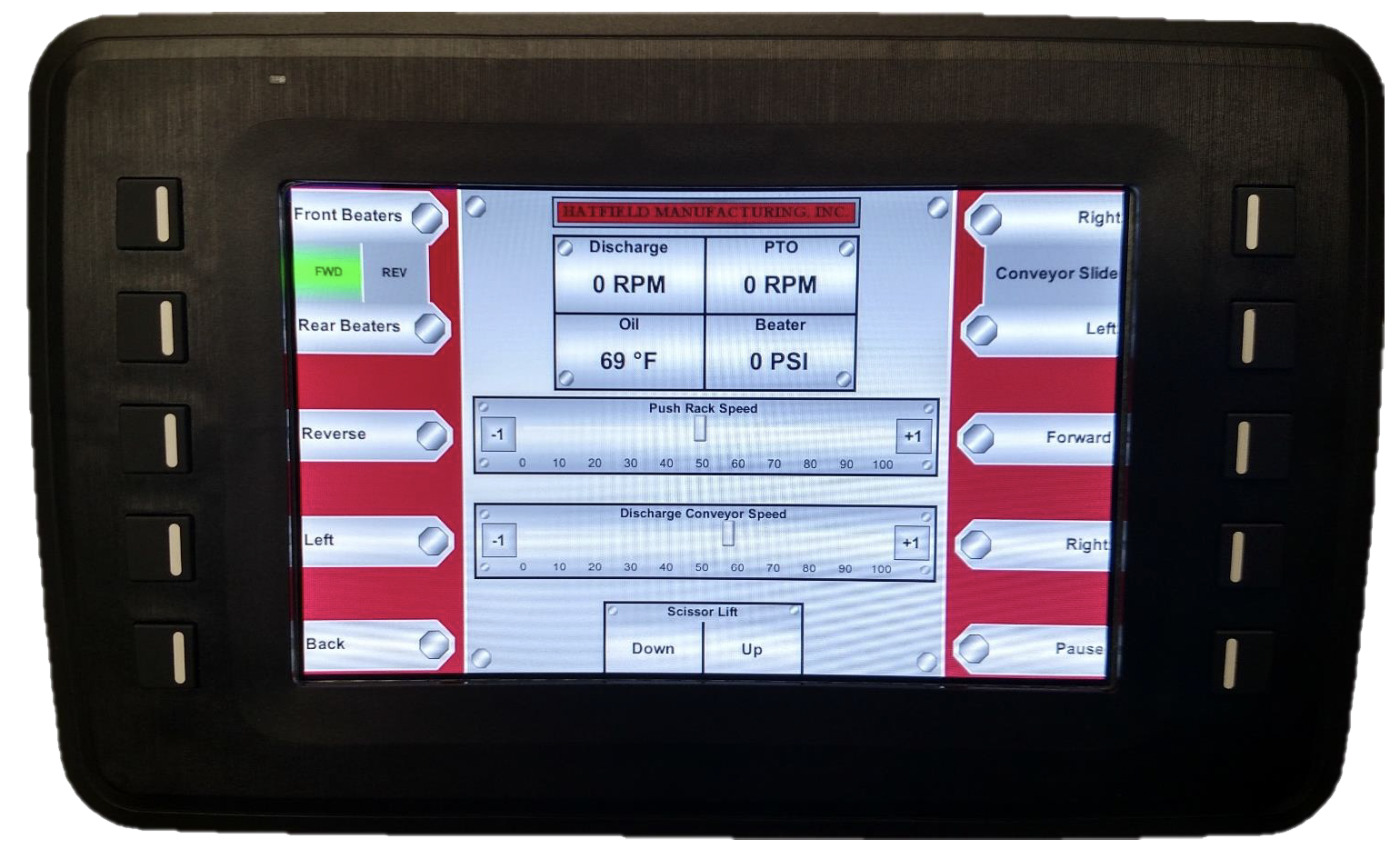
- The Central Readout carries forward from the Main Menu into this mode as well as Operating Mode.
- Some Manual and Operating Mode buttons “toggle” push it once to turn it on and again to turn it off. Other buttons work only as long as you hold them down. In both cases the whole button or the octagon on the button will light up green while active.
- Front and Rear Beaters: The upper left two buttons are for turning on the beaters. Clicking or tapping on either one will start the selected beaters turning. Clicking the same one again will shut them off. Clicking on the other set of beaters while one is active will switch which one is on. The system will not run both at the same time. In between the beater buttons is a forward/reverse option that can be switched by tapping on the desired direction. Forward is on by default and it is not necessary put the beaters in reverse during normal operation.
- Right and Left Conveyor Slide: The upper right two buttons move the front conveyor. Hold down either of these buttons until the conveyor moves as far as you want it to in that direction. The conveyor does not need to be fully extended in order to dispense out of that side.
- Push Rack Controls: The next two buttons down and the slide in between them control the Push Rack direction and speed. Similar to the Beater Controls, if you push the Forward button, the push rack will start to move forward. If you then push Reverse it will switch directions. If you push Reverse again while it is active the push rack will stop.
- The slider in between the buttons controls the speed at which the push rack moves. You can adjust it by tapping on the gauge at the speed you want. Fine adjustments can be made by tapping the “-1” and “+1” buttons at either end. This can be done while the push rack is in motion or stopped.
- When the push rack reaches the end of its travel, it will stop automatically. The word “MAX” will appear under the button that corresponds to the direction it was traveling in.

- Conveyor Controls: The next two buttons control the front conveyor belt that ejects the shredded straw out to the side. Again, you can choose left or right and you can switch between them. To shut the conveyor off you simply press the button for the active direction again to toggle it off.
- Like the Push Rack, the slider in between the buttons can be used to adjust the speed while the conveyor is running or stopped.
- Back: The Back button will return you to the previous menu.
- Scissor Lift: In the bottom center of the screen are the elevating controls that raise the upper deck of the trailer up to 30” of extra height. The height can be adjusted while the trailer is running, allowing for fine adjustment without having to stop.

WARNING
When trailer is elevated, especially with straw bales, it becomes very top heavy. Never activate the lift mechanism when trailer is on a slope or drive on uneven terrain with the lift raised.
- Pause: Push this button to stop the Push Rack, Beaters and Conveyor without losing your settings! This is very useful if you have a gap where no straw is needed or need to drive to the next row of pens, etc.
- The Pause button can also be pushed first before selecting beaters and push rack and conveyor directions. Then, when you have everything set and you are driving past the first spot to spread straw, hit the pause button again and everything will startup all at once!
Operating Mode

- Operating Mode is very similar to Manual Mode, it just simplifies operation by selecting some features for you. Here we will just highlight the differences, so make sure you read those pages.
- The Front and Rear Beater buttons now say Front and Rear Feeding.
- Front Feeding: When you push this button the Push Rack buttons will disappear because the system knows to set it to forward motion. The slider is still on screen so you can adjust the speed of the push rack. You will also need to select a conveyor discharge direction and speed.
- Rear Feeding: When you push this button the Push Rack is set to Reverse and the buttons disappear. Also, the Conveyor controls disappear as the conveyor is not used in Rear Straw Spreading.
- While the system is Paused the Push Rack buttons return and become “Push and Hold” controls so that Push Rack can be adjusted.
MAX Functionality
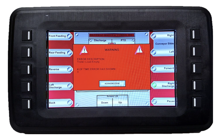
- While in operating mode, if the push rack hits the “MAX” position at the front or rear of the trailer (meaning all of the material has been processed and the trailer is empty). The following screen will appear.
- The push rack will now automatically travel to the other end of the trailer in anticipation of more material being loaded on to be processed in the same manner.
- All other controls work the same as in Manual Mode.
Diagnostics Screen

- The Diagnostics Screen is a two-column list of the historic faults and active faults. Both sides can be cleared off as you desire. This screen is live and updates every 5 seconds.
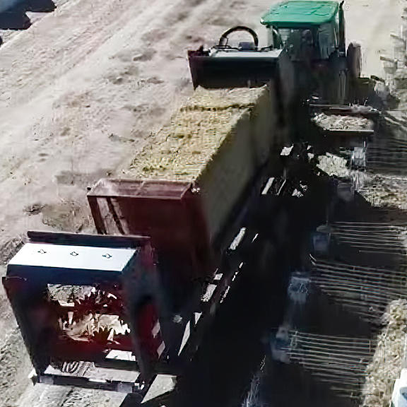
Loading Straw Bales
- Before putting straw bales on the Ultralift, you need to decide if you are going to be using the rear beaters or the front beaters and side conveyor. If you are going to be using the rear beaters to spread straw out the back of the trailer, then you need to move the push rack to the front. Conversely, if you want to use the front beaters and conveyor to spread straw out to one side or the other the push rack must be moved to the back. Care should be taken when loading bales to not damage the trailer with the loader. Don’t forget to cut the baling twine off before starting to process the straw through the machine!
Maintenance
Lubrication
- The Ultralift has 33 lubrication points (plus the PTO shaft) on it that all require the same high-quality bearing grease. See the chart for maintenance schedule.
| Part | # of points | How Much | How Often | Location |
|---|---|---|---|---|
| Conveyor Bearings | 4 | 1 pump | Weekly | Outside corners of the front conveyor |
| Elevating Links | 8 | Until it pushes out the ends of the links | Monthly | 4 on each elevating link, access from the underneath trailer |
| Front and Rear Beater Shaft Bearings | 12 | 2 pumps | Monthly | On the outside of the beater housing, some are under the red covers |
| Floor Drive Bearings | 4 | 1 pump | Monthly | Holes in the front and back of the top deck |
| Tires | 4 | 2 pumps | Quarterly | Under the center cap of the wheel hub |
| Tires | 4 | 2 pumps | Quarterly | Under the center cap of the wheel hub |
| Jack | 1 | 2 pumps | Yearly | On the front face of the Jack near the top |
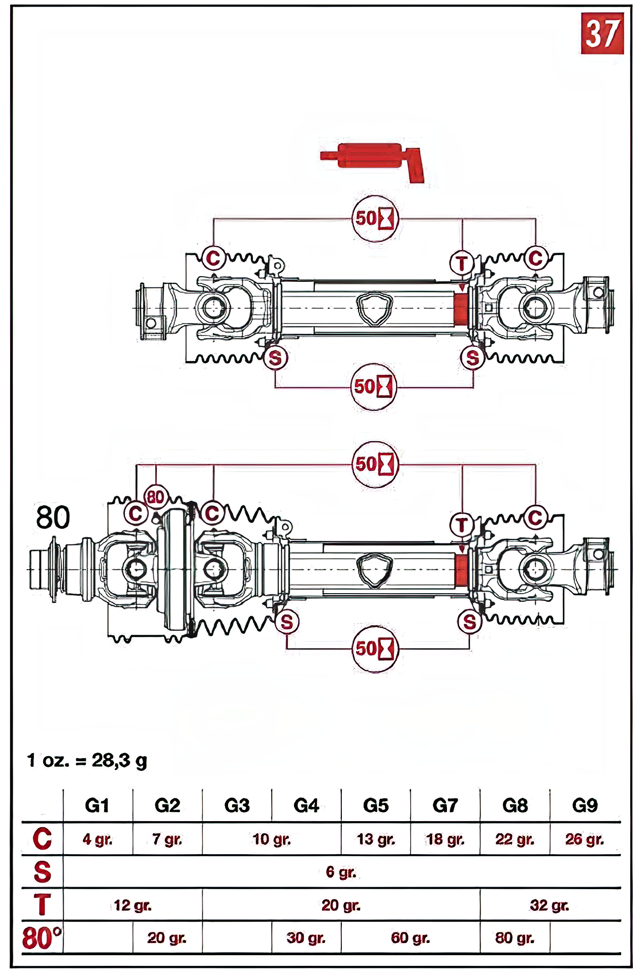
| PTO Drive Shaft | See Appendix A | See Appendix A | 50 hours of operation | See Appendix A |
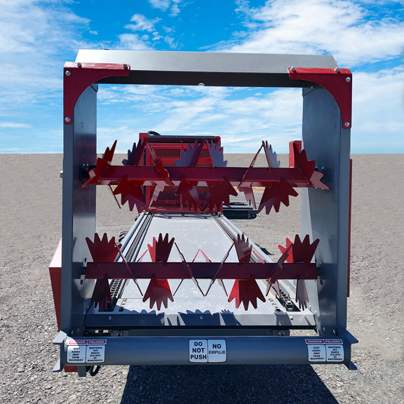
Sickle Knives
- The sickle knives on the front beaters are reversible and should be flipped when they begin to dull significantly. When the second side dulls they should be replaced. Periodically check for loose sickle knives and tighten them down.
- The rear beater blades are permanently affixed.
Floor Drive Chains
- The Floor Drive chains should be checked seasonally for tension. With the trailer unloaded and the push rack in the center, go to the back of the trailer and with a flashlight, look down the return tubes on the underside of the trailer and check to see that the floor chains are at least 1/2 in. up from the bottom of the tube at their lowest point.
- If they need to be tightened, first loosen the two bolts on the floor drive bearing and the jamb nut on the end of the floor drive tensioner.
- Turn the tensioner nut clockwise until the floor chain reaches the desired tension.
- Retighten the jamb nut and the two bolts on the floor drive bearing to a torque of 50 ft-lb.
- Make sure to Follow this procedure for both floor chains. After adjusting the second chain recheck the first to make sure it is still adjusted correctly.
Appendix A
Main Office & Manufacturing
1823 Shoestring Road | Gooding, Idaho 83330 | Toll Free: 800.359.8171 | 208.934.5182 | Fax: 208.934.8892
Sales | Parts | Manuals | Financing | Our Company | Contact Us
2025 Hatfield Manufacturing, Inc.