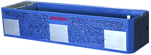
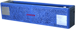
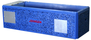
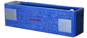
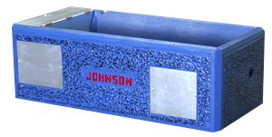
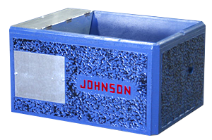
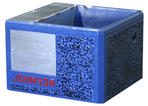
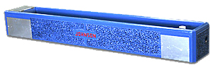
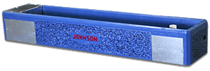
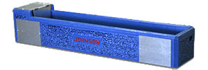
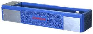
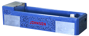
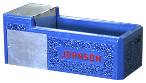
Johnson Water Troughs

Image
Image
Standard J Features
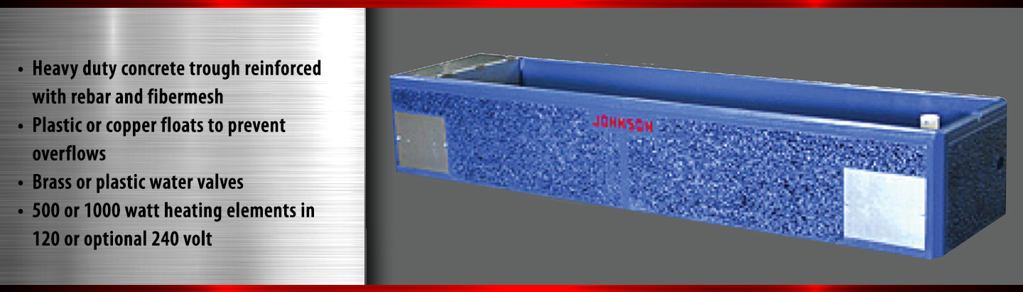
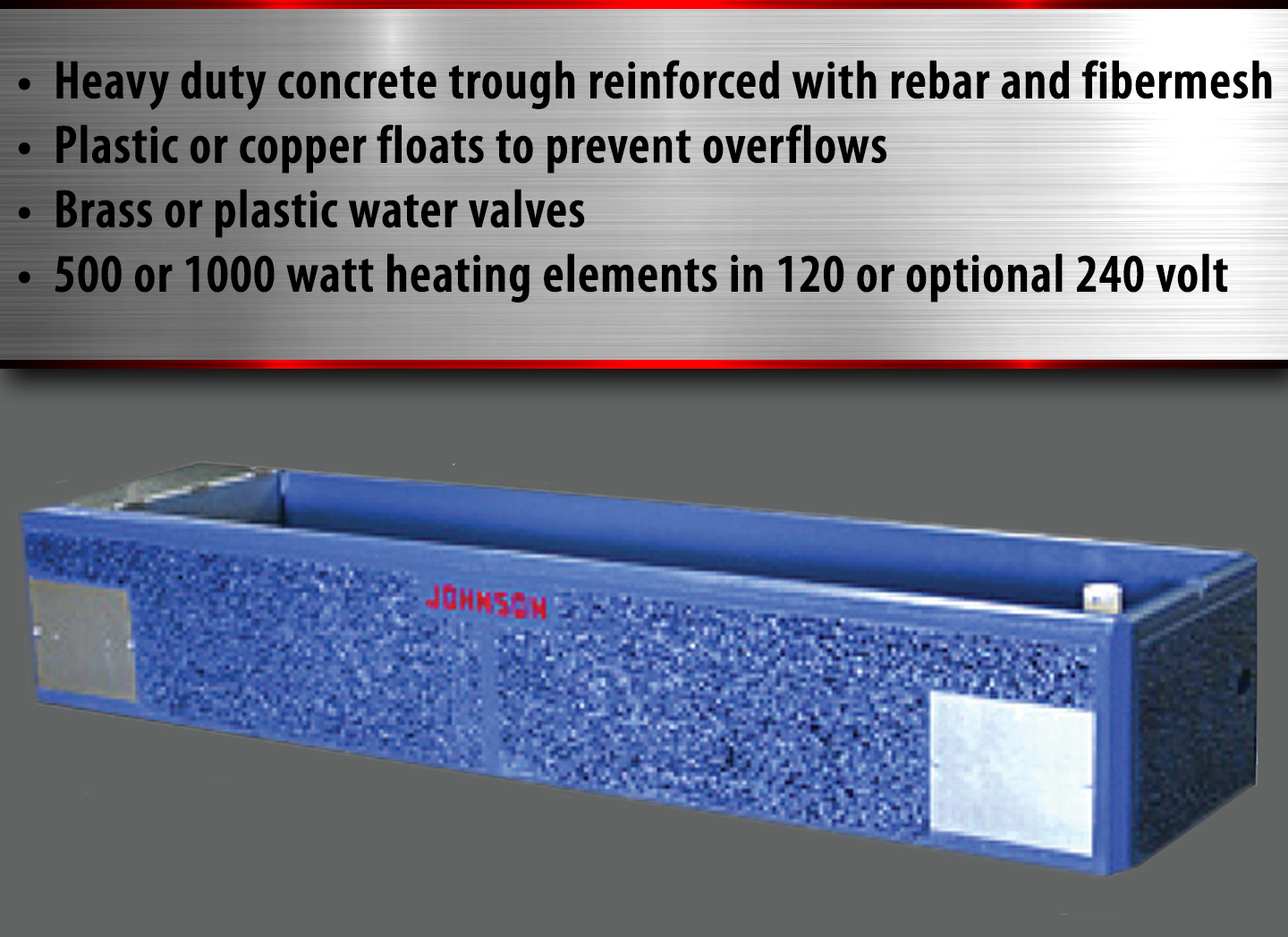
  • Heavy duty concrete tank (3/8" rebar and fibermesh)
  • Safe, quick and easy to lift and set
  • Epoxy painted trough and outside
  • Chamfered edges
  • Notched top for controlled overflow
  • Brass or plastic water valves
  • Brass float system (Stainless steel available)
  • Low profile hood to reduce cattle rubbing wear
  • Galvanized and hinged hood to protect valves (Stainless steel available)
  • Stainless steel hinges and rivets
  • Large galvanized side access door for easy hook ups (Stainless steel available)
  • 1" stainless steel water inlet coupler
  • Sloped trough bottom with 3" rubber plug for fast and easy cleaning
  • Polyurethane insulation sprayed on under trough for efficient operation
  • CSA Approved
Constant Flow J Models
  • Brass needle valve installed in addition to float valve for overflow (PVC available)
  • 5" Polypropylene floats
  • 3" Overflow coupler (2" Available)
  • Galvanized support bracket for overflow pipe (Stainless steel available)
  • Optional ice preventing valves available for saving water
Electric J Models
  • 5" Copper Floats
  • 500 or 1000 Watt heating element - 120 volt (240 volt optional)
  • Adjustable brass thermostat

J1680W

Image

35" W x 168" L x 28" H - 240 Gallons - 4350 lbs

J1440W

Image

35" W x 144" L x 25" H - 200 Gallons - 3730 lbs

J1440N

Image

23" W x 144" L x 28" H - 95 Gallons - 3070 lbs

J1200W

Image

35" W x 120" L x 25" H - 160 Gallons - 3040 lbs

J1200N

Image

23" W x 120" L x 28" H - 72 Gallons - 2600 lbs

J960

Image

35" W x 96" L x 28" H - 98 Gallons - 2610 lbs

J940

Image

23" W x 96" L x 28" H - 55 Gallons - 1990 lbs

J850

Image

23" W x 85" L x 26" H - 50 Gallons - 1670 lbs

J720

Image

35" W x 72" L x 25" H - 68 Gallons - 1910 lbs

J480

Image

35" W x 48" L x 25" H - 45 Gallons - 1400 lbs

J360

Image

35" W x 36" L x 25" H - 20 Gallons - 1060 lbs

J144

Image

21.5" W x 143.5" L x 18" H - 70 Gallons - 1955 lbs

J120

Image

26" W x 120" L x 18" H - 85 Gallons - 1800 lbs

J99

Image

21.5" W x 100" L x 16" H - 30 Gallons - 1275 lbs

J94

Image

23" W x 94" L x 18" H - 55 Gallons - 1400 lbs

J85

Image

21.5" W x 85" L x 16" H - 25 Gallons - 1100 lbs

J74

Image

24" W x 74" L x 14" H - 23 Gallons - 950 lbs

J48

Image

21.5" W x 48" L x 16" H - 15 Gallons - 690 lbs

Wiring & Operating Instructions

The thermostat is pre-set at approximately 45°. However sometimes during shipment or handling, the setting may become altered and must be reset. CAUTION: One complete turn of the adjusting screw on the thermostat changes the temperature setting by 80°. Several turns on the adjusting screw may ruin the thermostat and void the standard one-year warranty. Turn the adjusting screw counterclockwise (as if removing a screw) to raise the temperature setting; turn clockwise to lower temperature setting. Temperature range of thermostat is 0° to 175° F.
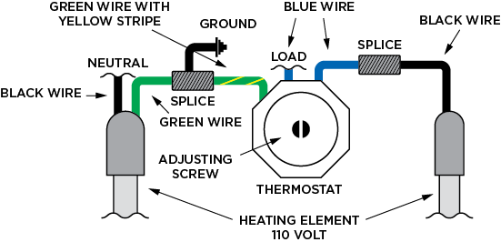
Safety First – This Unit Should Be Properly Grounded.
1) Connect one thermostat lead to one heating element lead.
2) Connect remaining thermostat lead to incoming hot wire.
3) Connect neutral heating element lead to incoming neutral wire.
4) Connect heating element ground wire to thermostat ground wire, then to a grounded stake.

In the event thermostat sticks or fails to function, which can occur after several years in service or after a period of non-use, turn adjusting screw 1/4 turn each way a few times. In many instances, this will activate the points and thermostat will function properly. If after this procedure the thermostat still doesn’t work, it will have to be replaced. IMPORTANT: Before replacing thermostat, check your heating element by following TEMPORARY EMERGENCY MEASURE INSTRUCTIONS.

Image

If thermostat fails during freezing weather, water can be kept from freezing by wiring direct.
1) Disconnect electric power to waterer.
2) Remove insulation from thermostat (two solid color) wires and place two bare connections together and tape.
3) Replace thermostat as soon as possible as element will draw electricity continuously and heat the water. CAUTION: Thermostat is screwed into 1/2″ P.V.C. coupling and should be turned only a little more than hand tight.

  1. Sensing tube is gas filled and must never be cut or submerged completely under water.
  2. When adjusting unit, follow these steps:
1) Open 1/8” needle valve.
2) Turn adjusting cone counterclockwise until a free flow of water emits from outlet. Adjust needle valve to desired flow.
3) Now turn adjusting cone clockwise until water stops and continue to turn approximately 1/8 turn. This should set unit at your pressure at a few degrees above freezing. (To test unit: Place an ice cube on the sensing coil. When the sensing tube senses the ice, water will begin to flow from outlet. Remove the ice-the water will stop.)
4) Fill water tank to your desired level.
5) Form sensing tube coil so approximately 1/2″ of the coil is submerged in water and the other 1/2 is exposed to the air at the point of overflow.


Image

1" Plunger Assembly - JCP19D

21.85

Image

Image

3/4" Plunger Assembly - JCP19

15.85

Image

Image

1" x 3/4" PVC Adapter with Constant Flow Ball Valve - JCP39-PVC

35.00

Image


Image

1" x 3/4" PVC Adapter with Constant Flow Needle Valve - JCP39

21.35

Image

Image

3" PVC Plug - JCP13B

7.00

Image

Image

1" Valve Complete - JCP18D

54.90

Image

Image

1" Valve Constant Flow - JCP18D-CF

71.90

Image

Image

3/4" Brass Valve Complete - JCP18B

39.90

Image

Image

3/4" Brass Valve Complete - Constant Flow - JCP18B-CF

56.90

Image

Image

1" Rubber Drain Plug - JCP15

2.10

Image

Image

2, 3 & 4" Rubber Plugs

4.85

Image


Image

5" Copper Float - JCP27

62.50

Image

Image

6" Copper Float - JCP27B

62.50

Image

Image

5" Plastic Float - JCP27A

14.55

Image

Image

6" Plastic Float - JCP27C

16.20

Image


Stainless Steel Stems
Image

JCP26-SS - 3.5'' Stem

4.88

Image

Image

JCP26C-SS - 4.5'' Stem

4.88

Image

Image

JCP26-SS - 6'' Stem

5.15

Image

Image

JCP26A-SS - 8" Stem

5.48

Image


Image

JCP26-SS - 10'' Stem

6.72

Image

Image

JCP26-SS - 12'' Stem

7.20

Image


Image

1" x 3/4" Brass Bushing - JCP38

7.15

Image

Image

Brass Thumb Screw - JCP25

2.12

Image

Image

Street Elbow, 45 Degree, 1/8" Brass - JCP30

4.45

Image

Image

1/4" Brass Needle Valve with T-Handle - JCP34T

13.80

Image


Image

Brass Long Arm - JCP23

7.35

Image

Image

Brass Short Arm - JCP22

5.30

Image

Image

Bolts with Washers 3/8" x 3/4" - JCP68

.25

Image

Image

3/8" Stainless Bolts with Stainless Washers - JCP68-SS

.57

Image


Image

Brass Cotter Pin - JCP24

.51

Image

Image

1/2" Galvanized Plug (Threaded) - JCP29

1.14

Image

Image

Thermostat 120V/240V - JCP28

106.90

Image

Image

Copper Tube - JCP67

7.90

Image

Element Clips
Image

JCP17 - Element Clip fits: J360, J480, J74, J720, J85, J850, J940, J960, J1200N, J1200W, J1440N, J1440W, J1680W

2.30

Image

Image

JCP17B - Element Clip fits: J48, J74, J85, J94, J99, J120, J144

3.75

Image

Heating Elements
Image

JCP16F - Heating Element 500 Watts 120 Volts Fits: J48, J74, J85, J99

45.65

Image

Image

JCP16C - Heating Element 1000 Watts 120 Volts Fits: J850, J1200N, J1440N

45.65

Image

Image

JCP16B - Heating Element 500 Watts 120 Volts Fits: J360

45.65

Image

Image

JCP16 - Heating Element 500 Watts 120 Volts Fits: J480, J720, J960, J1200W, J1440W, J1680W

64.30

Image


Image

JCP16L - Heating Element 500 Watts 240 Volts Fits: J48, J74, J85, J99

45.65

Image

Image

JCP16D - Heating Element 1000 Watts 240 Volts Fits: J850, J1200N, J1440N

45.65

Image

Image

JCP16K - Heating Element 500 Watts 240 Volts Fits: J360

45.65

Image

Image

JCP16A - Heating Element 500 Watts 240 Volts Fits: J480, J720, J960, J1200W, J1440W, J1680W

64.30

Image

Hood Assembly
Image

JCP36-2 - Galvanized Hood Assembly fits: J1200W, J1440W, J1680W

118.30

Image

Image

JCP84-SS - Stainless Steel Hood Assembly fits: J120

110.15

Image

Image

JCP57 - Galvanized Hood Assembly fits: J48, J144

68.50

Image

Image

JCP36 - Galvanized Hood Assembly fits: J480, J720, J960

102.20

Image


Image

JCP57 - Galvanized Hood Assembly fits: J48, J144

68.50

Image

Image

JCP35 - Galvanized Hood Assembly fits: J74, J850, J94, J1200N, J1440N

70.00

Image

Image

JCP84-SS - Stainless Steel Hood Assembly fits: J120

110.15

Image

Image

JCP36-2-SS - Stainless Steel Hood Assembly fits: J1200W, J1440W, J1680W

211.90

Image


Image

JCP37-SS - Stainless Steel Hood Assembly fits: J360

165.80

Image

Image

JCP36-SS - Stainless Steel Hood Assembly fits: J480, J720, J960

175.80

Image

Image

JCP57-SS - Stainless Steel Hood Assembly fits J48, J144

104.95

Image

Image

JCP35-SS - Stainless Steel Hood Assembly fits: J74, J94, J940, J1200, J1440

100.00

Image

Stainless Steel Overflow Pipe Brackets
Image

JCP52-SS - Stainless Steel Overflow Pipe Bracket fits: J360, J480, J720, J960, J1200N, J1440N

30.60

Image

Image

JCP52C-SS - Stainless Steel Overflow Pipe Drain Bracket fits: J1200W, J1440W, J1680W

30.60

Image

Image

JCP52A-SS - Stainless Steel Overflow Pipe Drain Bracket fits: J48, J74, J85, J850, J94, J940, J99, J120, J144

30.60

Image

Overflow Pipes
Image

JCP51-7 - 7" Overflow Pipe fits: J48

6.05

Image

Image

JCP51-8 - 8" Overflow Pipe fits: J74, J85, J99, J120, J144

6.52

Image

Image

JCP51-9 - 9" Overflow Pipe fits: J360

7.11

Image

Image

JCP51-10 - 10" Overflow Pipe fits: J850, J94, J940

7.32

Image


Image

JCP51-11 - 11" Overflow Pipe fits: J1200N, J1440N

7.76

Image

Image

JCP51-12 - 12" Overflow Pipe fits: J480, J720, J960

8.18

Image

Image

JCP51-14 - 14" Overflow Pipe fits: J1200W, J1440W, J1680W

9.03

Image

Galvanized and Stainless Steel Side Access Doors
Image

Galvanized Side Access Door 14.75'' x 13.5'' - JCP3

28.80

Image

Image

Galvanized Side Access Door 16.75'' X 10'' - JCP3B

30.10

Image

Image

Galvanized Side Access Door 16.75" x 13.5" - JCP3A

32.65

Image

Image

Galvanized Side Access Door 22.75''x 13.5'' - JCP3C

53.95

Image


Image

Stainless Steel Side Access Door 14.75'' x 13.5'' - JCP3-SS

53.50

Image

Image

Stainless Steel Side Access Door 16.75'' x 10'' - JCP3B-SS

41.30

Image

Image

Stainless Steel Side Access Door 16.75" x 13.5" - JCP3A-SS

56.80

Image

Image

Stainless Steel Side Access Door 22.75''x 13.5'' - JCP3C-SS

73.35

Image


Main Office & Manufacturing

1823 Shoestring Road | Gooding, Idaho 83330 | Toll Free: 800.359.8171 | 208.934.5182 | Fax: 208.934.8892

2024 Hatfield Manufacturing, Inc.